Energy Recovery System
The Energy Recovery System we developed aims to extract the residual heat from the flue gases of your gas-fired boiler installation. This residual heat, or energy, is normally lost into the atmosphere. By putting this heat to good use in one of your processes, the efficiency of your installation will be increased.
Generally speaking, every percentage increase in your efficiency will also result in a proportionate saving in your energy consumption. You make an important contribution to the environment through the lower flue gas temperature and fewer CO2 emissions. The design is based on the counter-flow principle whereby the water inlet takes place on the side of the flue gas outlet, thus achieving maximum efficiency. The ERS is characterized by its compact construction, versatile integration options, high efficiency and low flue gas resistance.

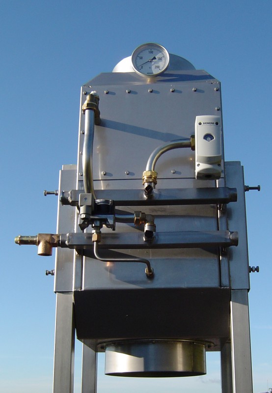
The ERS concept is based on years of experience and developed as a compact unit, complete with adjustable legs for vertical installation, making it easy to install in both existing and new installations. Flue gas side made of stainless steel 304.
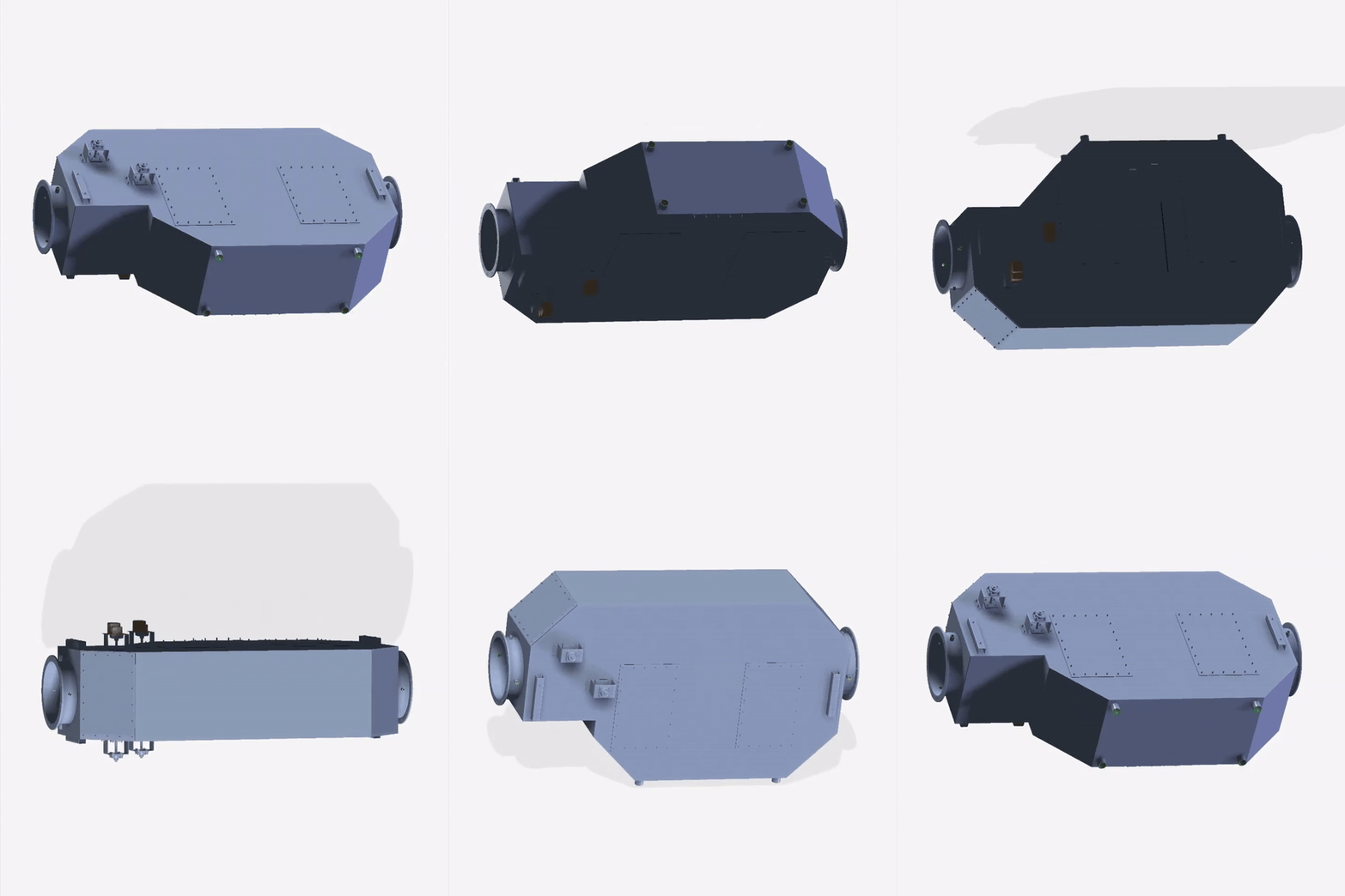
When set up in line with your chimney, the flue gases flow straight through.
In the event that the flue gases must be able to flow through at right angles, an alternative inlet connection is provided.
In the vertical arrangement, provisions have been made to guide the falling condensation water to the condensation drain connection, thereby preventing return into the chimney flue. For a simple performance of a flue gas side inspection, an inspection hatch is fitted on the inlet side.
The connections on the water side are symmetrical, allowing you to choose whether to connect on the left or right. Both the water inlet and outlet are equipped with a robust distributor and each have a temperature sensor, the outlet distributor also has a spring-loaded blow-off safety device. The cooling block is made entirely of stainless steel 316 and is equipped with aluminum fins for optimal heat exchange on the flue gas side. The cooling block is removable and interchangeable.
The control of the ERS is optionally digital and equipped with a display, which shows the water inlet and outlet temperatures, statuses and operating hours. Control of the circulation pump, display and registration of alarm messages such as maximum flue gas side resistance or maximum water temperature, with the option to retrieve the history.
As an extra addition, a heat meter can be included where the supplied heat is registered. When used on a steam boiler for heating the boiler feed water, a blowdown valve is included which will open in the event of overheating to allow the inflow of cooler water.
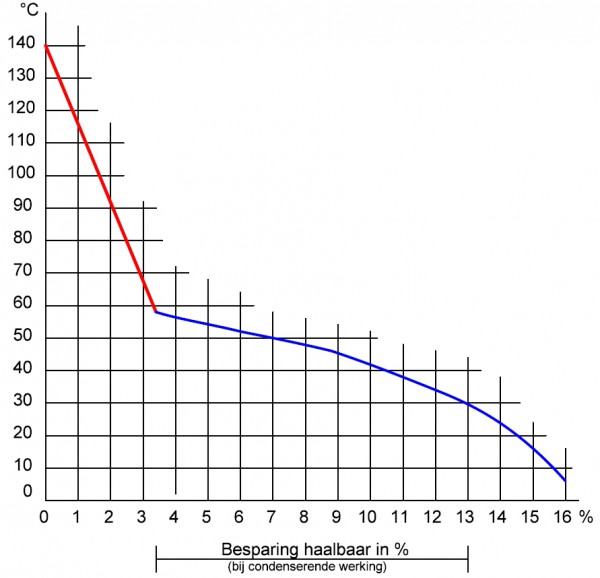
When used on a hot water boiler installation, we recommend choosing a water inlet temperature that is as low as possible, preferably below 45°C. This is a circuit that can use low-quality heat such as underfloor heating or preheating a hot water supply. When the flue gases condense, you extract the maximum amount of heat from the flue gases. When used in the return water of a heating group or boiler, it is possible that the water temperature is above the condensation limit and the efficiency is significantly lower. The condensation limit of flue gases is on average 58°C. When used on a steam boiler installation, we recommend circulating the boiler feed water from the storage tank. Cold feed water must enter through the storage tank, direct entry into the exchanger is not permitted and will cause irreparable damage. Warranty claims will hereby lapse. The amount of energy released from the ERS will decrease as the flue gas outlet temperature increases. See graph. With non-condensing operation, the saving is between 1.0 and 3.2%. With condensing operation the saving is between 3.3 and 13%.

133 / 5.000 Vertaalresultaten Vertaalresultaat Application behind boiler installations from 50 kW. Versions are increasing in capacity. For a selection, see our data sheet ERS.


